|
Mr. Erich Kowald has near Markt Hartmannsdorf erected a very noble observatory itself in Styria. The private observatory private observatory Posiberg is a 2-storey building in a massive construction, well insulated and plastered white with level control room and novel cylindrical wooden dome (sheet metal Disguised and manufactured to our own design). The approximately 4m wide dome can already house a big Cassegrain. It is currently fitted temporarily with a 10 "SC telescope.
 | 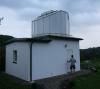 | 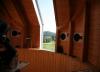 |  | | Southwest view | Northwest view | dome inside | control room |
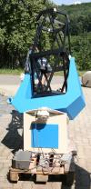
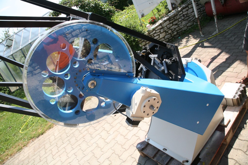
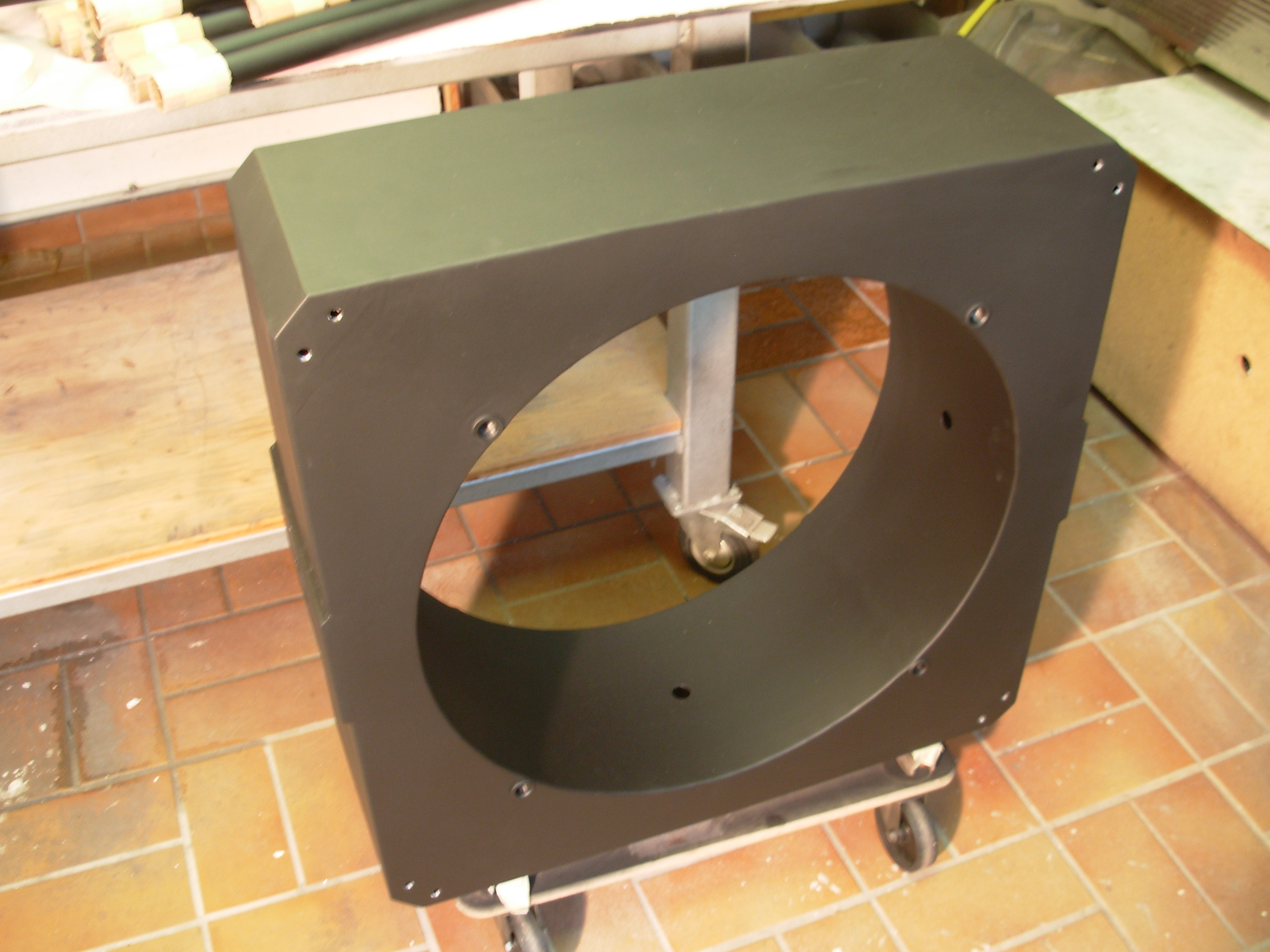
Before he went, however, to the production of his own telescope, it has already made two fork mounts for their private 40cm-Newton for club colleague of the local astronomical society Astroclub Auersbach. He has gone out of Rudolf Pressberger's plans of our 50cm-RC, has the fork arms slightly extended and adjusted the fork length to the existing truss-tube of Newton. Friction drive and bearing of tube and fork are original Pressberger type. While the first of these two mounts was still equipped with a somewhat idiosyncratic gear motor with belt drive, at second mount, the original Pressberger self-made gearbox unit was used in both axes now. The following pictures give an impression of this second telescope
:
 |
 |
 |
 |
 |
 |
 |
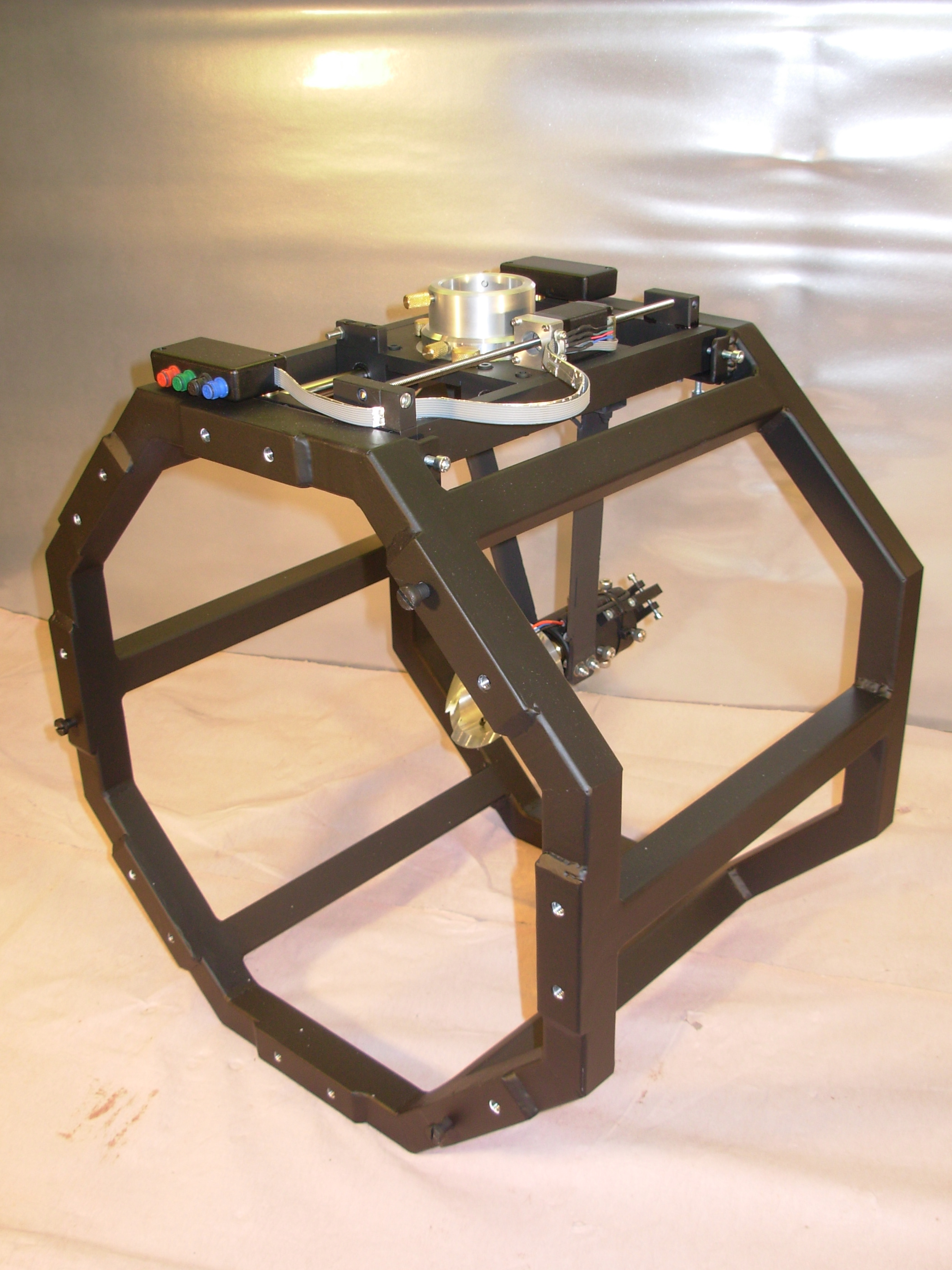
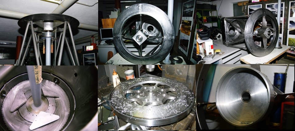
| 1 total view |
DE friction wheel |
3 DE bearing |
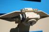
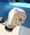
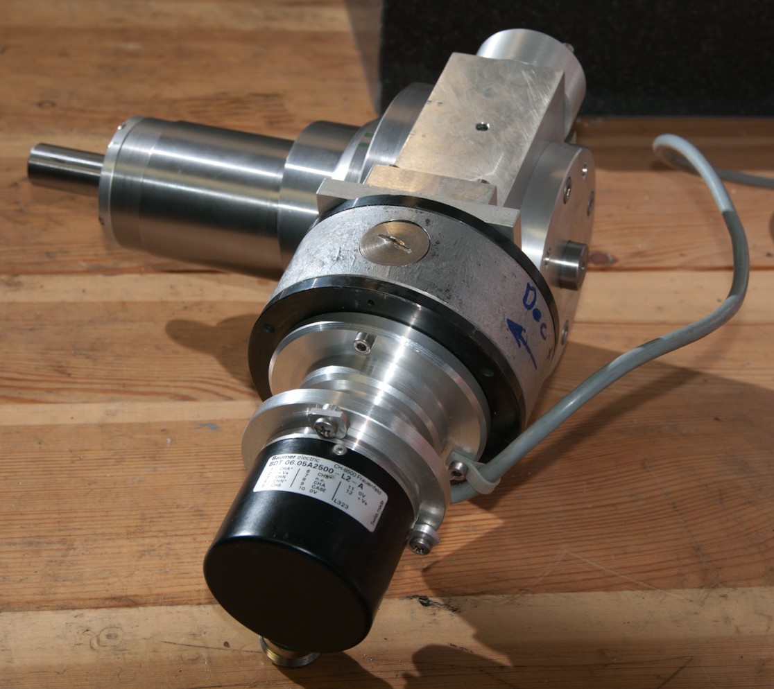
4 RA gearbox |
5 RA drive |
6 DE gearbox |
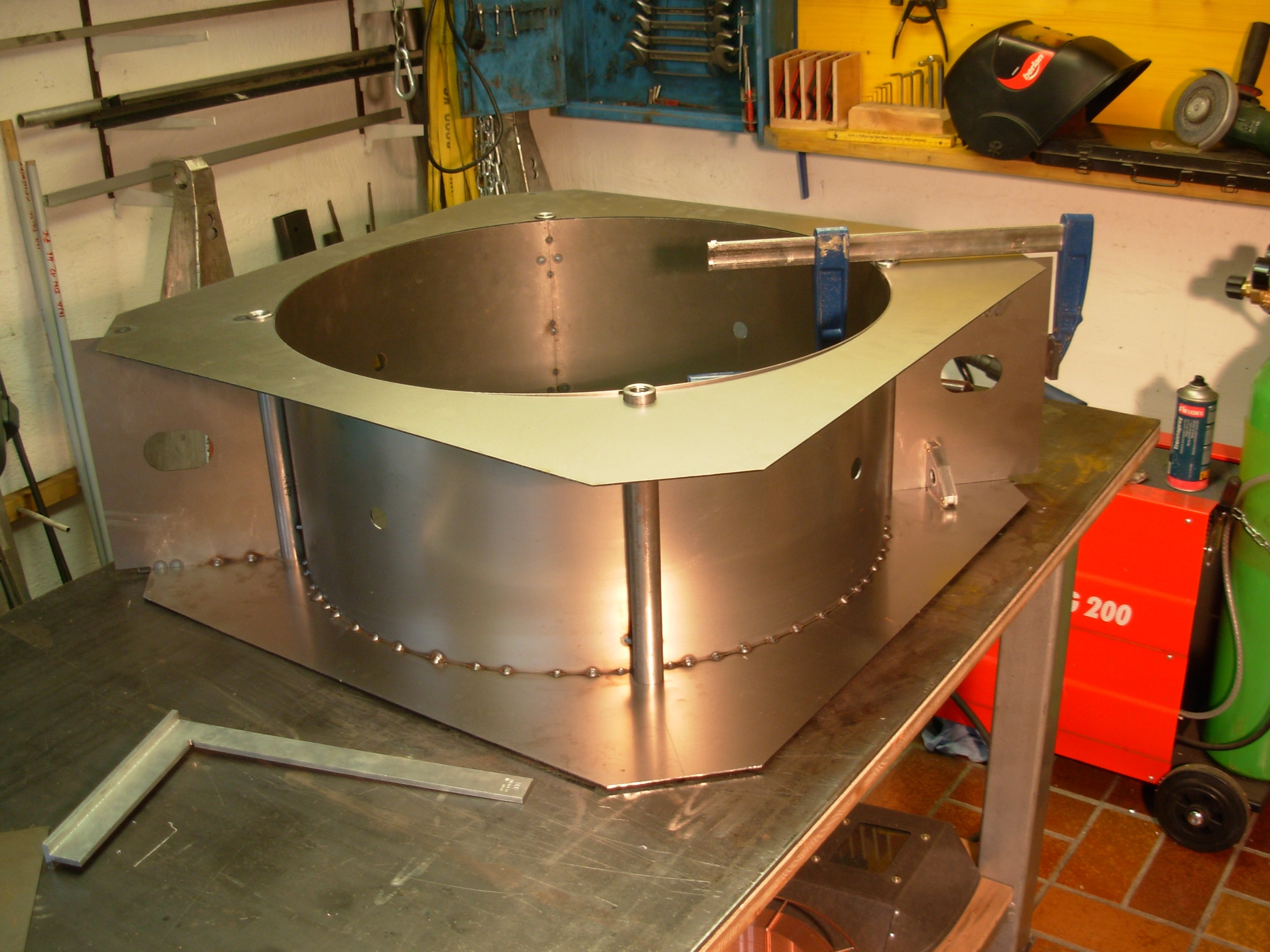
assembling |
This oneself has the construction in detail further developed as follows:
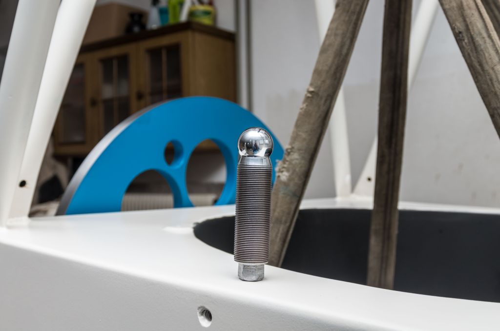
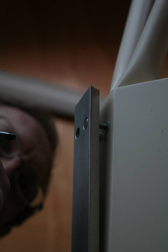
- In right ascension additional levers facilitate the adjustment between the drive shaft and the 50cm friction wheel
(see Figure 4 and 5) - Both transmissions were equipped with a additional mechanical clutch which can solve the helical teeth cogwheel seated on the friction wheel-drive shaft. Connoisseur of Pressberger construction know what is talked about here. The clutch can be actuated from the outside via a screw in the concentric drilled friction-wheel drive shaft (visible in Figures 4 and 6). It allows free pivoting of the tube by hand and facilitates the balancing of the telescope. In the GoTo mode, they may not be solved, of course, otherwise the control computer is lost the position of the telescope. Maybe it manages the Styrian colleagues by manually to follow the ISS by hand, we will see.
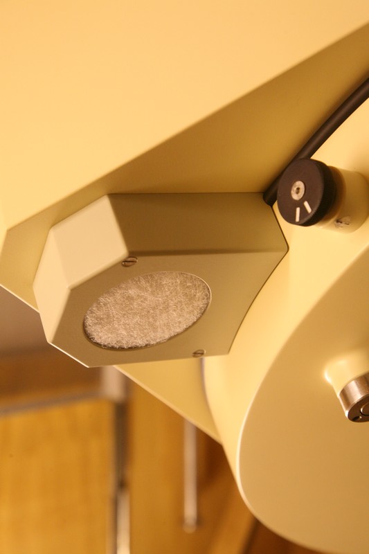
- The friction wheel for rektascension RA has received a wooden dust cover. (see Figure 5)
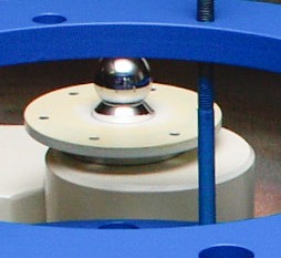
- The friction wheel for declination DE is provided with weight-saving holes which hintan keep distortion during hardening process of steel. (see Figure 2 and 3)
- An graceful transparent housing protects the DE friction wheel from contamination and it provides a view of the beautifully crafted wheel. (see Figure 2 and 3)
In place of the servo motor/encoder unit in conjunction with the Stoll telescope control (used for our telescope), powerful stepper motors are used in Styria (see Figure 4 and 6). They are powered by a conventional cooking FS2 type control from germany with micro-step operation.
Furthermore, Erich Kowald has developed a simple to implement method for adjusting the friction wheel drive. Together with our method (it is based on an idea by M. Stoll but not described), there are now two ways to friction-adjustment avaliable.
The experience gained during the construction, Erich Kowald now benefit for his own telescope. Certainly which is not a newton but already a real 50cm Cassegrain as it should be for a professionally built observatory. With so much exercise in telescope making Erich can manufacture its telescopic fork in record time locally in its own way, great equipped workshop. In contrast to the telescopes of his two colleagues in the club, is also the optical tube manufactured from Pressberger-type. This instrument is thus a purebred Pressberger-like telescope, in design and size comparable to the telescope of the Kepler observatory in Linz and our own telescope. Therefore, Erich has the Harpoint Observatory paid a visit in June 2007. So he could see it in full size and Natura and not just on the screen as you draw 3D animation in the CAD program. Also in the tube, Erich has some specialties. So the spider with the secondary mirror is replaceable designed to easily replace them later against a primary focus camera.
Finally, we show three views of Erich's drawing of the Pressberger-like secondary mirror unit. These are screenshots of his detailed Cad-representation, using different angles seen (copyright Erich Kowald):
The difference between Figure a and b can be seen only on the colorful arrows of the coordinate directions (approximately in the middle). This is due to the symmetry of the construction. The eye of the beholder finds two solutions for the interpretation of foreground and background. Firstly, the secondary mirror cell white below appear to stand in the foreground. The second solution of the form perception recognizes the green subscribed focus gear unit as the observer facing. Who has the images viewed by the construction of our own telescope in the gallery exactly further recognizes the bending sheets of absolutely shifting-free focusing unit, further the adjusting device for the secondary mirror and the drag arm for the limit switches of the focus gear unit (at our own telescope there is one drag arm only). The Spider plates are standing away in the drawing
Some experts came together in Harpoint. People who understood why the construction of R. Pressberger works so well and who are ready to proceed to doing. As another visitor we welcomed Mr Hannes Schmidt with us, chairman of the association Astroclub AuersBach in Styria. He has written a nice visit report on the web page of the association.
 |
The experts in Harpoint
From left to right clockwise: Howdii, Andrew, Armin, Hannes, Erich, Christian.
My chair is empty, one had to take the picture yes. |
A few weeks later I was able to pay a return visit to Erich in Styria (together with Howdii). The images shown here were created there.
Mr. Hans Heinrich Wenk from Losenstein (Upper Austria) was also interested on the construction of such a mount.
We wish the new Pressberger-type telescope makers a lot of success in the practical implementation and we hope that we can further report here soon.
Thus, there will be soon in Austria more then 12 observatory-telescopes that are wholly or largely designed by Pressberger. In Germany there are already one Pressberger-type fork mount. Follow us, people!
|


")


 Old DSLR cameras have no live video display on the rear LCD screen just as you would expect from small digital cameras. The current generation of DSLR cameras, alternatively to the optical viewfinder come up with a live image display. This does not mean at all that one can also see so deep-sky objects with the camera on the telescope. We have developed a removable electronic viewfinder for DSLR cameras, which can. He works with an external monitor, it saves so the neck sprains and protects his intervertebral discs. On top of that our viewfinder can be easily reconstructed. A detailed description can be found


, the original flange (right)")


")


